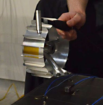
Figure 1: Inverted chassis prepared for hammer testing
A roving hammer test is the simplest way to determine natural frequencies of a structure.
The structure is tapped with a small hammer, and the resulting frequencies are sensed through instrumentation. It is a bit like striking a bell and sensing the frequency of its vibration by observing the resulting tone. To survive the shaking of launch, it is important for MoonRanger’s lowest frequency to be above 100 Hz, which is only achieved by being sufficiently stiff and light.
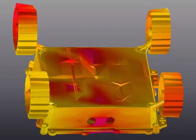
These roving hammer tests revealed MoonRanger’s natural frequencies and the corresponding mode shapes (Figure 1). The testing turned MoonRanger upside down, bolted it in the manner that will attach it to its lander, and tapped on its belly. This resulted in response frequencies of 107, 119, and 170Hz (Figure 3). The resulting mode shapes (Figure 2) agree with results from Ansys dynamic analysis, but the frequencies at which these modes occur contrast with results from earlier vibration tests.
Separate testing was conducted by tapping a wheel module. The modes detected agreed in shape and frequency with results from vibration testing and Ansys dynamic analysis. The first mode for the old wheel module was 127 Hz (vs 135 Hz from vibration testing). The first mode for the new wheel module (with 60mm width wheel) was 142 Hz.
Figure 1.5: Blue wires convey data from accelerometers for measuring the frequency and magnitude of vibration. The handheld hammer is shown prior to tapping the inverted chassis.
Figure 2 - Areas of maximum displacement shown in red for MoonRanger’s 1st mode