Early design enclosed the electronic printed circuit boards in aluminum boxes for radiation protection, and attached the boxes to the rover’s top deck for rejecting heat from the electronics to black space. The problem arose when the number of printed circuit boards increased to the point that their boxes would no longer fit on the top deck.
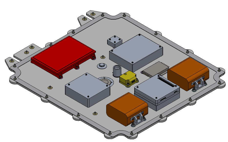
When more electronic boards than initially anticipated were needed, there was no longer sufficient space to mount the many boxes spread out under the robot’s top deck. For this reason, a new design mounts up to 10 boards (more than needed) and two batteries in one structure. The new design decreases volume occupied by the boards, simplifies wire harnessing, and exhibits superior thermal regulation. The solution is superior by way of volumetric capacity, harnessing simplicity, thermal regulation.
Gallery
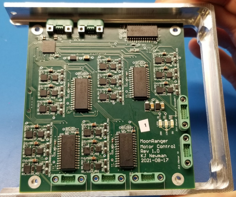
A motor controller board is mounted in one ‘slice’ of the ‘loaf’ structure. All the printed circuit boards comply with this PC104-like form factor for standard assembly.
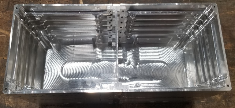
Two stacks of 5 PCB mounts each are illustrated (top middle and left). A battery is mounted in each of the two thicker half-boxes (right and bottom). Hence, the structure compactly mounts up to 10 PCBs and 2 batteries.
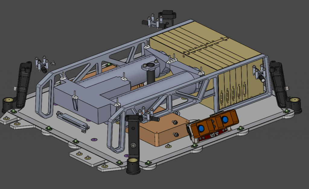
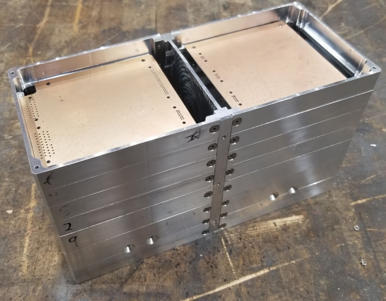
This partial assembly of the structure shows all the interlocking PCB mounts and the closed battery compartment on the far end.
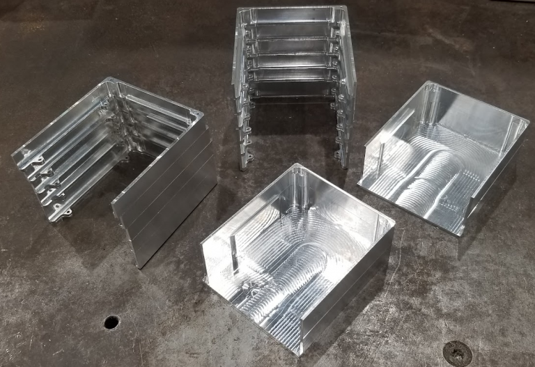
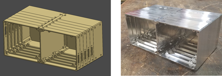
Loaf module designed (left) and assembled (right). Note the center partition that precludes interference, if any, between the two board cavities. A cover plate completes the assembly.
Two mock-PCBs rest in the top slice of the assembled loaf.