
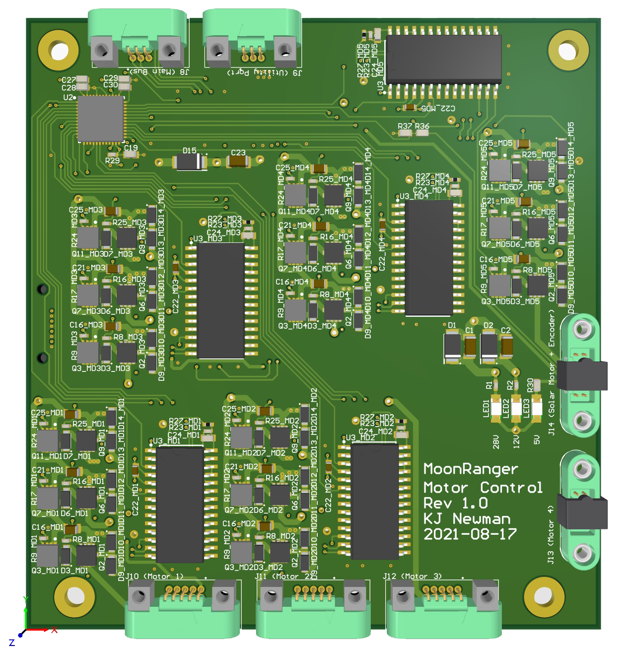
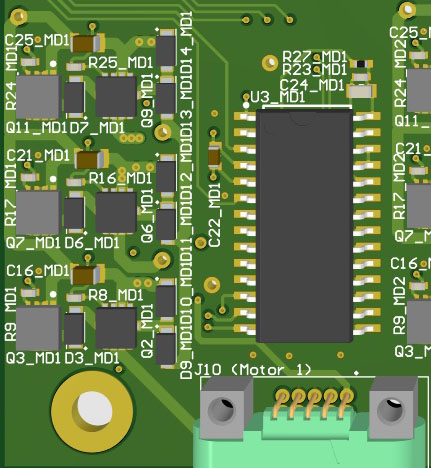
 Each of these modules controls one of MoonRanger’s five motors and processes motion commands into the voltages and currents that power a motor.
The large black commutation chip accepts three input commands: rotating clockwise or counterclockwise, setting the speed, and setting the duration of the intended motion. The chip generates signals corresponding to the motor’s three phases, but at a low voltage with power levels far too small to drive a motor. The signal for each of the three phases passes through an amplifier that generates the strong signal that drives one of the motor’s magnet coils. The three signals from the three phases spin the motor. The three sets of three amplifiers are located to the left of the large black commutation chip. The large green connector conveys the drive signals to the motor’s wires. The Hall sensor feedback reports the motor’s rotation. The current’s feedback is proportional to the torque the motor had to apply to achieve its work.